Whale Tail (FreeWili) · Volume 1
Whale Tail (FreeWili) — Volume 1
Introduction
The Whale Tail Badge by FREE-WILi is unusual among conference badges in being almost entirely about field-bus / industrial communication protocols. Where the typical badge gives you LEDs + WiFi, Whale Tail gives you 10BASE-T1L Ethernet, CAN FD, RS485 Modbus, and a 4–20 mA sensor simulator. These are not toy choices — they’re the protocols a controls engineer or industrial-IoT developer encounters on Monday morning.
This volume walks through each physical layer, why it exists, what makes the silicon Whale Tail chose interesting, and how to exercise each one with the badge. Vol 2 covers the RP2040 firmware architecture (how 3 protocols share one chip’s SPI buses and PIO state machines). Vol 3 is the protocol-exercise cookbook.
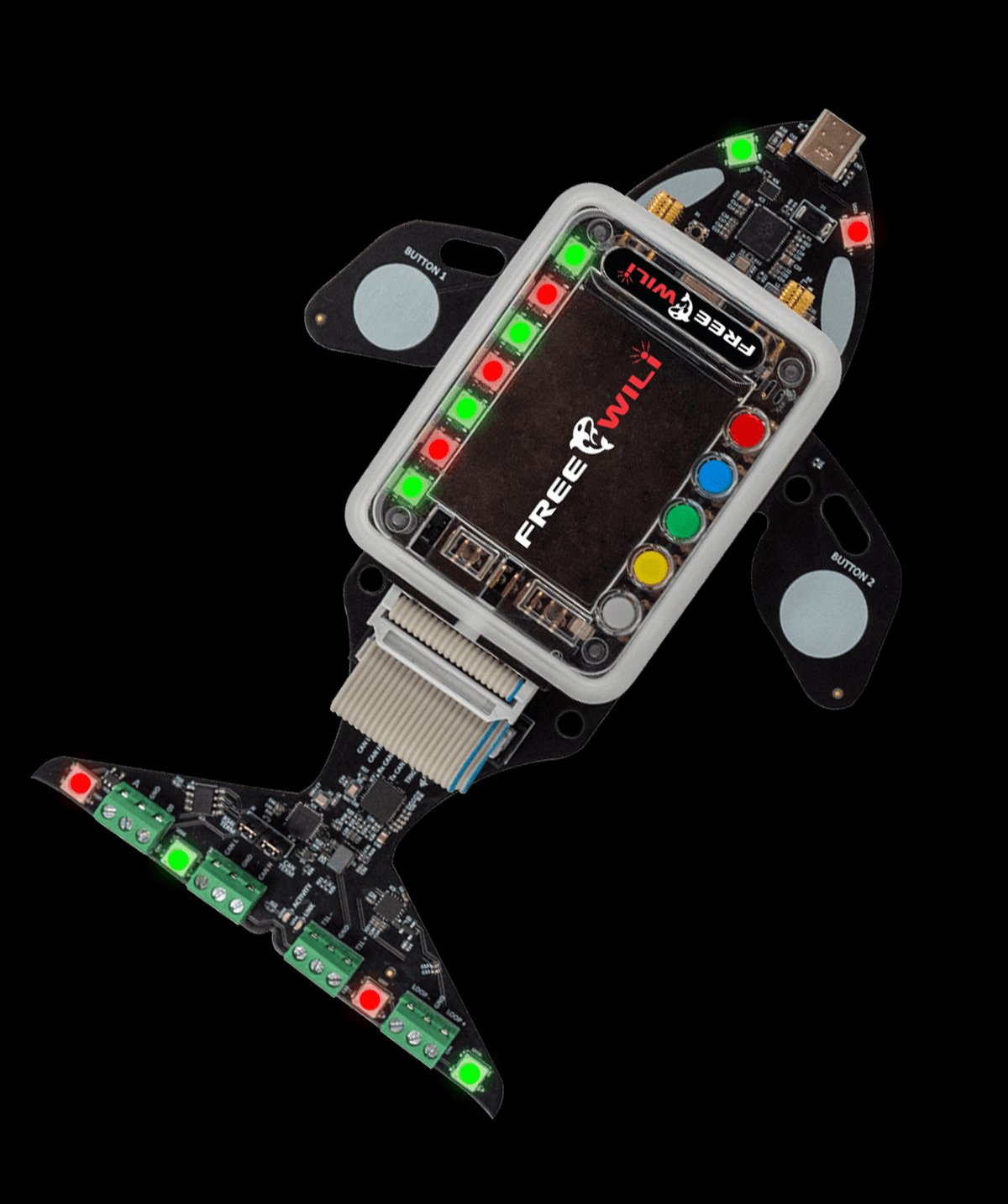
📷 Hero photo:
03-outputs/figs/whale_tail_hero.jpg(TBD — pull from vendor product page).
1.1 The host: RP2040
- Dual ARM Cortex-M0+ @ 133 MHz
- 264 KB SRAM, external QSPI flash for code
- 2 × PIO blocks, 4 state machines each = 8 PIO state machines total — important here because PIO can bit-bang protocols when SPI is busy
- 2 × SPI, 2 × I²C, 2 × UART on hard peripherals
- USB 1.1 + UF2 bootloader
The choice of RP2040 (not RP2350) is interesting. The RP2350 has more PIOs (12 vs 8) and a more capable CPU — but RP2040 is cheaper, well-supported, and 8 PIOs is plenty for this badge. Likely also a design-lifecycle choice (Whale Tail predates or overlaps RP2350 availability).
1.2 10BASE-T1L (single-pair Ethernet)
1.2.1 What it is
10BASE-T1L is the IEEE 802.3cg-2019 amendment that brings Ethernet to single twisted pair at 10 Mbps over up to ~1 km, optionally with power (similar to PoE but for SPE — “Single-Pair Ethernet”). It’s positioned to replace the venerable 4–20 mA current loops and HART in modern industrial process control: same cabling profile (simple twisted pair, no shielding required), but Ethernet semantics all the way to the sensor.
The “L” in T1L is “long-reach.” There’s also a 10BASE-T1S (short, multidrop) variant aimed at automotive — different chip family.
1.2.2 The silicon: Analog Devices ADIN1110
- Integrated MAC + PHY in one chip — appears to the host as an SPI peripheral with an Ethernet-frame interface
- 10BASE-T1L compliant, with intrinsic safety variants for hazardous-area use
- Hosts (like the RP2040) read/write Ethernet frames over SPI — no separate MAC needed
- Power consumption is low enough for genuinely battery-driven endpoints
1.2.3 What you can do with it on Whale Tail
- Link up to another 10BASE-T1L peer — a second Whale Tail, an ADIN1110 eval board, or a vendor T1L switch
- Run any TCP/IP stack on top (lwIP, picotcp, MicroPython’s network stack)
- Capture frames with recent Wireshark for T1L decode
Caveat: single Whale Tail can’t link to itself — you need a peer. Plan accordingly.
1.3 CAN FD
1.3.1 What it is
CAN FD (Controller Area Network with Flexible Data-rate) is the 2015 update to CAN 2.0. It keeps the multi-master broadcast bus + arbitration model of classic CAN but adds:
- Higher data-phase bit rates (up to ~5 Mbps in practice, though physical-layer limited by bus length and transceivers)
- Larger payload (up to 64 bytes vs CAN 2.0’s 8)
- CRC improvements
Standard ISO 11898-1. It’s the modern automotive bus (every car now), and it’s making inroads into industrial machinery too.
1.3.2 The silicon: Microchip MCP2518FD
- SPI-attached CAN FD controller (not transceiver — Whale Tail will have a transceiver next to it, identify from schematic)
- Two TX + 31 RX FIFOs, message-acceptance filters
- The MCP2518FD is widely used in hobby/educational CAN-FD work, notably the CANIS Labs CANPICO board (also RP2040 + MCP2518FD). Whale Tail is explicitly noted as CANPICO-compatible — meaning CANPICO firmware should run, and SocketCAN/PCAN tooling works.
1.3.3 What you can do with it on Whale Tail
- Run a 2-node CAN-FD bus (Whale Tail + another node) with 120 Ω termination at each end
- Sniff with
candump(SocketCAN) or PCAN-View - Practice bit-timing math (BRP, prop seg, phase seg 1/2, SJW) — the perennial source of CAN bus headaches
1.4 RS485 + Modbus
1.4.1 What it is
RS485 is the granddaddy of industrial multi-drop differential signaling. Up to 32 (or more, with modern transceivers) nodes on a twisted pair, half-duplex, robust over hundreds of meters at moderate baud rates.
Modbus-RTU is the binary application-layer protocol that dominates field-device communications, riding on top of RS485 (or RS232). Master/slave (Modbus calls them “client/server” now), with function codes for read-coil / read-register / write-register / etc.
1.4.2 What you can do with it on Whale Tail
- Implement a Modbus-RTU master and address a Modbus slave (e.g., a flow meter, a VFD)
- Implement a Modbus-RTU slave and respond to a master’s polls (use
modpollorpymodbuson a laptop) - Practice the termination-and-fail-safe biasing dance that catches every first-time RS485 user
1.5 4–20 mA sensor simulator
1.5.1 What it is
The 4–20 mA current loop is the analog protocol RS485 + 10BASE-T1L are trying to replace, but it’s still the dominant convention for industrial analog sensors: 4 mA = 0% reading, 20 mA = 100% reading, with the NAMUR NE 43 convention adding 3.6 mA / 21 mA as “sensor fault” signals.
Whale Tail can act as a fake sensor — drive any current in the range. Useful for testing the other side of an industrial system (the PLC analog input card, the SCADA configuration).
1.5.2 What you can do with it on Whale Tail
- Drive a calibrated current into a current-sensing input
- Sweep through a measurement range to validate scaling
- Inject fault signals (3.6 mA “down-scale burnout”, 21 mA “up-scale burnout”) to test alarm handling
Caveat: the simulator outputs current. A voltmeter on the wire won’t show you anything useful — you need a current-sensing receiver.
1.6 Auxiliary I/O
- 6 programmable RGB LEDs — likely WS2812-class addressable
- 2 capacitive touch sensors — for badge interaction
- FREE-WILi expansion plug — accepts FREE-WILi modules (display, power, wireless). The pinout is vendor-specific; document it in vol 2 from the schematic.
1.7 What stands out
- Three real industrial physical layers in one badge — most “industrial” badges pick one
- CANPICO compatibility is generous design — it means an existing tooling ecosystem (CANIS Labs’ tools) Just Works
- 4–20 mA simulator is the practical detail that elevates this from “Ethernet/CAN demo” to “useful for actual integration work”
- Modular via FREE-WILi plug — turns into a display/wireless tool when paired
1.8 The “why this badge” question
For a controls/industrial-IoT engineer, this is the badge that doubles as a permanent bench tool. The protocols here aren’t going away — 10BASE-T1L is just ramping up adoption, CAN FD is mainstream, RS485/Modbus will outlive us all, and 4–20 mA is the universal language of industrial analog. Building fluency with these on one $relatively-cheap-conference-badge is genuinely useful.
References
- Vendor product page: https://freewili.com/products/whale-tail/
- Vendor docs: https://whaletail.freewili.com/
- Schematics PDF: https://whaletail.freewili.com/schematics/ (pull into
02-inputs/research/) - ADIN1110 datasheet + AN-2433/2434 — Analog Devices
- MCP2518FD datasheet — Microchip
- IEEE 802.3cg — standards body (paywalled; OPEN Alliance has free intro material)
- ISO 11898-1 — CAN FD spec
- CANIS Labs CANPICO — for compatible firmware references
Comments (0)