Supercon 6 (2022) · Volume 3
Voja4 (Supercon 6, 2022) Volume 3 — The Python Toolchain
Assembler, disassembler, and Tkinter-based virtual machine — how every public tool for the badge actually works, where the gaps are, and how to contribute
Introduction
The 2022 Supercon 6 badge ships with no compiler. The CPU is 4-bit, the instruction word is 12 bits, the registers map directly to data memory, and the intended way to use the badge is to punch instructions into the front-panel buttons. But three Python tools — all in the upstream repo at Hack-a-Day/2022-Supercon6-Badge-Tools — make off-badge development practical:
Table 1 — The 2022 Supercon 6 badge ships with no compiler. The CPU is 4-bit, the instruction word is 12 bits, the registers map directly to data memory, and the intended way to use the badge is to punch instructions into the front-panel buttons. But three Python tools — all in the upstream repo at [Hack-a-Day/2022-Supercon6-Badge-Tools](https://github.com/Hack-a-Day/2022-Supercon6-Badge-Tools) — make off-badge development practical
| Tool | Author | License | Purpose |
|---|---|---|---|
assembler/assemble.py | Mike Szczys (2022) | MIT | Two-pass assembler. Reads .asm, writes .hex. ~1240 LOC, single file, zero non-stdlib dependencies. |
assembler/disassemble.py | Mike Szczys (2022) | MIT | Reverse the above. Reads .hex, writes .s. Shares constants and checksum logic with the assembler via from assemble import …. |
emulator/bvm.py + 3 supporting modules | Adam Zeloof (March 2022) | MIT | Tkinter-based Badge Virtual Machine. Loads a .hex file, simulates the CPU, and renders the badge face with every panel LED in its correct on-board location. Requires Python 3.10+, PIL/Pillow, Tkinter. |
This volume walks through how each one actually works — enough detail that you can patch a bug, add an instruction, write a custom front-end (e.g. a web assembler), or contribute (the emulator’s button handling is acknowledged-incomplete and the upstream README invites pull requests). The architectural reference is vol1; if a register name (PCL, RdFlags, EXR N) is unfamiliar, see vol1.md §2-3.
📷 Hero photo, ISA reference, and SFR table: see vol1.
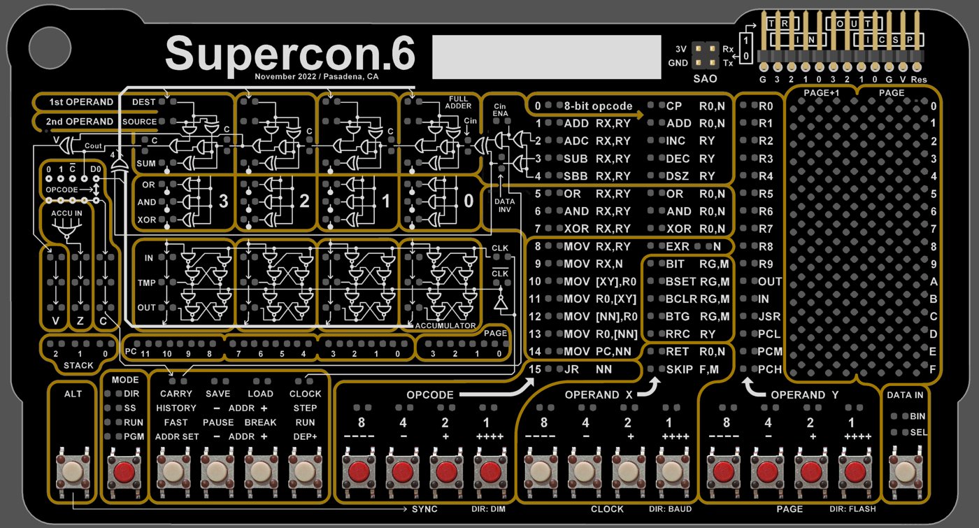
gui_assets/badgeface.jpg) that the Tkinter Badge Virtual Machine loads as its background — the emulator positions all 272 LED widgets over this render using the pick-and-place CSV, so each simulated LED lights at the exact spot it occupies on real hardware (see §5.2). This clean face render is the visual centerpiece of the Python toolchain's emulator. — Image: Hack-a-Day / 2022-Supercon6-Badge-Tools emulator assets (MIT) — https://github.com/Hack-a-Day/2022-Supercon6-Badge-Tools/blob/main/emulator/gui_assets/badgeface.jpg3.1 Repository layout
2022-Supercon6-Badge-Tools/
├── README.md                  Top-level project overview
├── assembler/
│   ├── assemble.py            ← The assembler. Start here.
│   ├── disassemble.py         ← The disassembler. Shares header+checksum with assembler.
│   ├── README.md              Tool usage
│   └── LICENSE.md             MIT (Mike Szczys, 2022)
├── emulator/
│   ├── bvm.py                 ← Tkinter GUI shell + LED-map driver
│   ├── badge.py               ← Badge wrapper: clock + step + hex-file loader
│   ├── bvmCPU.py              ← The 4-bit CPU (all 31 instructions, flags, stack)
│   ├── bvmParser.py           ← Pure function: 2 bytes → {op, args} dict
│   ├── requirements.txt       Pillow (PIL); Tkinter is stdlib
│   ├── gui_assets/            badgeface.jpg, pnp.csv (LED placement), LED on/off PNGs
│   └── LICENCE.md             MIT (Adam Zeloof, March 2022)  — note the spelling
├── manuals/                   The 5 official PDFs (covered in vol1)
├── firmware/Badge_v99r3.bin   The PIC24 host firmware — public binary, source not released
├── software/compiler/         Empty/aspirational. There is no high-level compiler.
├── examples/                  Several user programs (Hamlet, Tertis, Snake, Flappy, etc.)
└── tutorial/                  Six markdown tutorials covering Basics, Math, Flow, IO, Memory, Graphics
The tutorial/ directory is genuinely useful — particularly 5.Graphics.md for understanding the LED matrix and 4.Memory.md for the page/SFR model — but it’s narrative, not reference; vol1 is the canonical reference.
3.2 The assembler: assemble.py
3.2.1 Two-pass architecture
.asm source ──┐
              │
              ▼
        ┌─────────────┐
        │  Pass 1     │   Tokenize + build symbol table.
        │  parse_line │   Detect EQU, labels, ORG; advance reg_addr.
        │  per line   │   No code emitted yet.
        └─────────────┘
              │
              │  (code_array, symbols)
              ▼
        ┌─────────────┐
        │  Pass 2     │   Walk code_array. For each line:
        │  resolve +  │   - resolve SmartTokens against symbols
        │  emit       │   - call the matching Opcodes.opcode_*() method
        │             │   - convert (op, x, y) → 12-bit int
        └─────────────┘
              │
              ▼
        ┌─────────────┐
        │  generate_  │   Prepend 6-byte header
        │  hex()      │   Append 16-bit checksum
        │             │   Each instruction → 2 bytes (LE)
        └─────────────┘
              │
              ▼
        .hex output
The split is necessary because forward references exist. JR end and GOSUB myfunc both need to know end: and myfunc:’s addresses, which may not have been seen yet at the line of the jump. Pass 1’s job is to compute every symbol’s value (a program-memory address for labels, or the EQU literal); pass 2’s job is the actual instruction emission with substitutions resolved.
A subtlety: pass 1 has to predict how many machine words each source line will produce, because labels carry addresses, and a single source line can produce 2 or even more words (every pseudo-op except NOP/CPL R0). The double_opcodes list at assemble.py:281 enumerates the ones that consume 2 words; ASCII consumes 2 per character; ORG jumps the address counter forward by filling with 0x000 words. See the reg_addr accounting inside get_tokenized_code().
3.2.2 The tokenizer state machine
parse_line() (line 334) walks a finite-state machine to validate syntax. The states are:
Table 2 — parseline() (line 334) walks a finite-state machine to validate syntax. The states are
| State | Triggered when… | Accepts next |
|---|---|---|
OPCODE | start of line | An identifier; transitions to WATCH_TOKEN_SET |
WATCH_TOKEN_SET | after opcode/comma/[ | A token, [, or EQU |
TOKEN_COMMA_COMMENT | after a complete token outside brackets | , (more args) or ; (comment, end-of-instruction) |
TOKEN_COLON_BRACKET | inside […], ready for first token | A token or : (for two-register pair like [R1:R2]) |
TOKEN_BRACKET | inside […], after : | A second token or ] |
TOKEN_VAR_DEF | after EQU | The defining expression |
WATCH_COMMENT | after a label : (label assignment) | ; only |
The tokenizer accepts three flavors of modifying tokens:
- Keywords
LOW,MID,HIGH— nibble-select a value (used to load a 12-bit address into PCH/PCM/PCL one nibble at a time) - Operators
+,-— symbol arithmetic (e.g.JR label + 2) - Square brackets
[…]— bracket the operand to a memory-addressing instruction (MOV [XY], R0,MOV PC, [NN],JR [NN])
A SmartToken (a thin list subclass) holds the contents of a bracket-set or modifier-chain and defers resolution to pass 2. So JR label + 2 parses in pass 1 as a SmartToken(['LABEL', '+', '2']); pass 2 resolves LABEL against the symbol table and adds 2.
3.2.3 Symbol resolution: global labels, local labels, EQU
        ; Global label
        myproc:
            MOV R0, 0
.loop:                      ; local label — scoped to "myproc"
            INC R0
            JR .loop        ; resolves to myproc.loop

        ; EQU constant
        FRAMES   EQU 60
MOV R1, FRAMES ; assembled as: MOV R1, 60- Global labels (e.g.
myproc:) — written to thesymbolsdict at the currentreg_addr. The most recently seen global label is tracked inlast_label. - Local labels (e.g.
.loop:) — leading., stored aslast_label + ".loop"(i.e."myproc.loop"). When aJR .loopresolves, the assembler concatenates the current global label with the local name to look it up. This makes.loop,.next, etc. safely reusable in every subroutine. - EQU constants —
NAME EQU value; the value is resolved (it can itself be an expression of previously defined constants), and the symbol is stored.
The JR instruction has additional arithmetic baked into resolution: at assemble.py:617, target_line - relative_to_this_line_number - 1 is computed, with the -1 countering the badge’s PC auto-increment before the relative add. This is why JR label can resolve to a negative signed byte and still work.
3.2.4 Opcode encoding — case study: MOV
The MOV mnemonic in the Voja4 ISA covers six different machine instructions, all distinguished by argument shape:
Table 3 — The MOV mnemonic in the Voja4 ISA covers six different machine instructions, all distinguished by argument shape
| Source line | Encoding shape | Opcode (binary) | Method |
|---|---|---|---|
MOV RX, RY | 1000 XXXX YYYY | MOVRXRY=0b1000 | args_rxry path |
MOV RX, N | 1001 XXXX NNNN | MOVRXN=0b1001 | direct make_machinecode |
MOV [XY], R0 | 1010 XXXX YYYY | MOVXYR0=0b1010 | […] parse, two-reg branch |
MOV R0, [XY] | 1011 XXXX YYYY | MOVR0XY=0b1011 | […] parse, two-reg branch |
MOV [NN], R0 | 1100 NNNN NNNN | MOVNNR0=0b1100 | […] parse, literal branch |
MOV R0, [NN] | 1101 NNNN NNNN | MOVR0NN=0b1101 | […] parse, literal branch |
MOV PC, [NN] | 1110 NNNN NNNN | MOVPCNN=0b1110 | […] parse, tokens[1]=="PC" branch |
The dispatch happens in opcode_mov() (line 929). It checks whether any token contains a list (i.e. brackets were used), and if so, whether tokens[1]=="PC" (target is PC), whether R0 is among the tokens, and whether the bracket contents are all integers (memory address [NN]) or two register names ([XY]). The result feeds make_machinecode(opcode, oper_x, oper_y):
def make_machinecode(opcode, oper_x, oper_y):
    return (opcode<<8) + (oper_x<<4) + oper_y
That’s it — a 12-bit int. Pass 2 returns these as a tuple (each ASCII char or pseudo-op may produce several), and parse_asm() accumulates them into assembled_code.
Subtlety with
[XY]: in the source assembly this looks like one operand, but the encoded operand_x isreg_number(X)and operand_y isreg_number(Y)— i.e. the bracket notation[R3:R5]directly maps to two register-number fields of the 12-bit word. The colon between the two registers is not a label-creation colon; it’s the bracket-pair delimiter.
3.2.5 Pseudo-instructions
The assembler expands these into one or two real instructions:
Table 4 — The assembler expands these into one or two real instructions
| Pseudo | Expands to | Notes |
|---|---|---|
GOTO addr | MOV PC,[hi:mid] + MOV PCL, lo | 2 words; performs a long jump |
GOSUB addr | MOV PC,[hi:mid] + MOV JSR, lo | 2 words; writes to JSR triggers the subroutine call |
NOP | MOV R0, R0 | 1 word; chosen carefully — must NOT target PCL or JSR |
CPL R0 | XOR R0, 0xF | 1 word; complement R0 |
CPL RX, RY | MOV RX, 0xF + SUB RX, RY | 2 words |
NEG RX, RY | MOV RX, 0 + SUB RX, RY | 2 words |
LSR RY | AND R0, 0 (clears C) + RRC RY | 2 words |
SL RX, RY | MOV RX, RY + ADD RX, RY | 2 words |
RLC RX, RY | MOV RX, RY + ADC RX, RY | 2 words; rotate-left through carry |
ORG N | Fill PC up to address N with 0x000 words | The fill words are bit-pattern 0, which decodes as CP R0, 0 — a benign side-effect for any addresses that may accidentally execute. |
ASCII "str" | Sequence of RET R0, n pairs (low nibble + high nibble) | 2 words per character. Forms a lookup-table that, when called via GOSUB tab + (R0 << 1), returns each character’s nibbles via the RET R0, N mechanism. |
BYTE N | Two RET R0, n (low, high) | For numeric lookup tables |
NIBBLE N | One RET R0, n | 4-bit-only tables |
The ASCII/BYTE/NIBBLE pseudos are the badge’s only practical way to put data in program memory — recall the Voja4 has no separate data ROM; data tables live in program memory and are read by calling them as subroutines (GOSUB) and letting RET R0, N return the table value in R0. This is why all three of those pseudo-ops emit RET R0, N instructions: each entry IS a one-instruction subroutine.
3.3 The .hex file format
The output of assemble.py is not Intel HEX. It’s a custom raw binary:
+---------+---------+----------+---------+
| Header  | Length  | Payload  | Cksum   |
| 6 bytes | 2 bytes | N×2 bytes| 2 bytes |
+---------+---------+----------+---------+

Header  = 00 FF 00 FF A5 C3
Length  = number of 12-bit instructions, little-endian
Payload = each 12-bit instruction packed into 2 bytes, little-endian
Cksum   = sum of (Length + Payload), low byte first, high byte first, mod 0x10000
The 0x00 0xFF 0x00 0xFF 0xA5 0xC3 header is a magic number — the host PIC checks it during a Load operation (DIR-mode SAVE/LOAD, 9600,N,8,1 over the I/O connector) before accepting a transfer. The simple word-sum checksum catches almost all single-bit serial errors; for higher reliability the host PIC also relies on UART parity.
Each 12-bit instruction is stored as 2 bytes:
byte_low  = 0000 NNNN   (lower nibble = oper_y; upper nibble = oper_x's low bits)
                          [actually: low nibble of byte_low = oper_y;
                           high nibble = oper_x]
byte_high = 0000 MMMM   (lower nibble = opcode; high nibble = padding = 0)
The bvmParser.parse() in the emulator reverses this:
opcode2 = get_bits(instruction[0], range(0,4))   # = oper_y
opcode1 = get_bits(instruction[0], range(4,8))   # = oper_x
opcode0 = get_bits(instruction[1], range(0,4))   # = opcode (4 bits)
padding = get_bits(instruction[1], range(4,8))   # MUST be zero
assert(padding == 0)
If opcode0 == 0, the instruction is an 8-bit-opcode extended instruction (sub-opcode in opcode1, single operand in opcode2). Otherwise it’s a 4-bit-opcode instruction.
The pack_hex_bytes() helper in the assembler is little-endian and 16-bit-wide; checksum() walks the payload as low/high pairs and accumulates the sum modulo 0x10000.
3.4 The disassembler: disassemble.py
A single Python file at ~260 LOC, mostly a flat dictionary lookup. It:
- Reads the file as raw bytes.
- Validates the 6-byte header and the trailing checksum (or
-fto force despite a checksum mismatch). - Walks the payload 2 bytes at a time, parsing
opcode0/opcode1/opcode2exactly as the emulator does. - Dispatches on
opcode0(or, if zero, onopcode1) into one of 31 handlers, each of which returns a string like"ADD R0,R5"or"BIT R2,0b10".
Format choices in the output:
- Immediates are printed in binary —
0b1101, not13or0xD— because the badge’s panel is binary, so when you’re reading the disassembled listing you’re matching it to what you’d press on the badge. - Bracket notation is preserved —
MOV [R3:R5], R0for the[XY]form. - The address column shows the 12-bit PC in hex (
%03X), and the instruction word is shown either with spaces between nibbles (0001 0010 0011, the-sflag) or solid (000100100011, the-wflag). Verbose mode (no flags) shows everything; specific flags suppress all but the requested columns.
The disassembler doesn’t attempt to recover labels — there’s no PDB-style symbol table in the hex file, so labels are lost on assembly. Round-tripping assemble → disassemble → assemble produces functionally equivalent code but with auto-generated identifiers, not the originals.
disassemble.py imports checksum and Registers from assemble.py, so the two files must live in the same directory. The disassembler’s named-register mapping is shared with the assembler’s — they both use Registers().named_registers from assemble.py:62.
3.5 The emulator: BVM (Badge Virtual Machine)
3.5.1 Module decomposition
                  ┌─────────────────┐
                  │     bvm.py      │  Tk window, LED widgets, frame timer,
                  │  (GUI shell)    │  LED map. Calls Badge.update() at 100 Hz.
                  └────────┬────────┘
                           │ owns
                           ▼
                  ┌─────────────────┐
                  │   badge.py      │  clock/timer loop, hex-file loader,
                  │    (Badge)      │  speed selection, opcode visualizer state
                  └────────┬────────┘
                           │ owns           ┌─────────────────┐
                           ├────────────────┤ bvmParser.parse │  Pure: 2 bytes
                           │                │  (one function) │   → instr dict
                           │                └─────────────────┘
                           ▼
                  ┌─────────────────┐
                  │  bvmCPU.py      │  The 4-bit CPU state. 256-nibble RAM,
                  │     (CPU)       │  PC, SP, V/Z/C, 31 instruction methods.
                  └─────────────────┘
Each layer has a clean responsibility:
-
bvmCPU.CPU(320 LOC) — pure CPU state and behavior. No GUI awareness, no clock awareness. Each instruction method (ADD,MOV, etc.) takes a dict of arguments produced by the parser and mutatesself.ram,self.pc,self.sp,self.V,self.Z,self.C. -
bvmParser.parse()(130 LOC, single function) — pure decode: takes a 2-byte instruction, returns a{op: str, args: dict, opcode0, opcode1, opcode2}dict. Theopcode0/1/2fields are passed along so the GUI can light up the corresponding opcode-display LEDs. -
badge.py— the time-stepping and I/O glue. Owns the program memory (progMem), the host-level timer, and the bit positions visible on the badge face that are separate from CPU state (page register0xF0, clock LED state, etc.). On eachupdate()call it checks whether enough time has passed (based on the speed selected via SFR0xF1) to advance one CPU step, then callsparse()and dispatches viagetattr(self.cpu, instruction['op'])(instruction['args']). -
bvm.BVM— the Tkinter shell. Loadsgui_assets/badgeface.jpgas the background andgui_assets/pnp.csv(the pick-and-place file from PCB manufacturing) to position every LED at its real physical XY coordinate scaled to the screen. On each frame it re-reads the CPU’sram,pc,sp, flags, and current opcode and sets each LED’s image to its on/off bitmap accordingly.
3.5.2 The LED map — why pnp.csv?
The badge’s LEDs aren’t on a regular grid — they’re scattered across the panel where they belong functionally (CLK is near the clock-speed knob, ACC is near the accumulator label, the memory matrix occupies the right half, etc.). Rather than hand-coding 272 LED coordinates, Adam parsed the pick-and-place CSV (the file the PCB factory uses to position SMT components) and used those XY coordinates directly. A scale factor + offset (scale = 20.73 / guiScale, x0 = 13, y0 = 4) maps from millimeters-on-PCB to pixels-on-screen, with Y flipped because PCB-Y is bottom-up and screen-Y is top-down.
This means the emulator’s LED positions are accurate to within sub-millimeter pick-and-place tolerance — when an LED lights in the emulator, it lights at the exact spot it would on a real badge. Very satisfying when debugging.
The LED map at the bottom of bvm.py (the giant block-comment from line 191) documents what each red LED 1-183 and each yellow LED 1-89 represents. This is the canonical reference for “which LED is which” — more detailed than the User Manual’s panel-callout figure.
3.5.3 Clock + scheduler model
The emulator runs at a fixed 100 Hz GUI frame rate (10 ms frameDelay). At each frame, Badge.update():
- Reads
cpu.ram[0xF1](the Speed SFR) and indexes into aspeeds[]array —[250e3, 100e3, 30e3, 10e3, …, 0.5]Hz, matching the badge’s 16 user-selectable clock steps from vol1 §1. - Checks whether
0.5 / self.speedseconds have elapsed since the last clock toggle. - If yes, toggles
self.clockbetween 0 and 1; on the rising edge (clock 0→1), it callsself.step()to execute one instruction.
So a 0.5-second-per-instruction setting on the badge translates to a clock that visibly toggles every 0.5 seconds on the emulator screen, exactly mirroring the front-panel CLK LED on real hardware. The slowest speed is 0.5 Hz, the fastest is 250 kHz, matching the hardware spec.
Badge.step() does the actual work: read progMem[pc], parse it, increment PC, then call the CPU method. If the program runs off the end of progMem, an EOFError is raised and the GUI scheduler exits — closing the emulator.
3.5.4 What’s faithful, what’s a shortcut
Faithful:
- All 31 instructions are implemented in
bvmCPU.CPU, with correct flag side-effects matched against the Instruction Set manual. MOV’s six modes, including the PCL/JSR write-triggers-jump behavior (handleJumpsinbvmCPU.py:69).- Stack semantics (
SPincrements before push, max depth 5, overflow/underflow raiseRuntimeError("Crash!")). EXR Nshadow-swap with Page 14.SKIP F,MwithF ∈ {C, NC, Z, NZ}andM ∈ {1..4}(whereM=4encodes asM=0, matching the assembler’s encoding atassemble.py:1039).JR NNsign-extends the 8-bit operand to negative offsets (signed(args['nn'], 8)inbvmCPU.py:294).- Random SFR (
0xFF) — re-randomized “every clock cycle” (actually every emulator frame, but close enough). - Clock speed selection via SFR
0xF1.
Shortcuts / gaps (real engineering opportunities):
- Button input is incomplete. There are
Buttonobjects placed on screen frompnp.csv, butButton.__init__only stores x/y — no click handler, no IN-register update. To get a program reading buttons working, you’d need to bind a Tkinter click event to each Button widget and route into the appropriate KeyStatus / KeyReg SFRs (0xFC/0xFD). BITon remapped IN. The code atbvmCPU.py:355readsself.ram[args['g']]directly — fine for R0-R3 in the 4-register subset of BIT/BSET/BCLR/BTG, but doesn’t honor the SFR-remap of IN/OUT controlled byWrFlags.IOPos.- OR with carry side-effect. The Instruction Set manual states
OR R0, NwithN=1“sets carry”; the implementation atbvmCPU.py:219always setsself.C = 1afterOR R0, N, which differs from the manual’s intent (only set carry if the carry-producing operation occurred). The code includes a# I think the docs are wrong herecomment — a contribution opportunity to either confirm the implementation against real-hardware behavior or fix it to match the documented semantics. ADCoverflow semantics. Similar comment atbvmCPU.py:147— Adam thinks the manual is wrong; behavior matches ADD’s overflow logic, not the docs.- No serial UART. SFRs
0xF5–0xF8(SerCtrl, SerLow, SerHigh, Received) are normal RAM; nothing actually transmits anything over a (virtual) wire. - No Save/Load. The 15 PIC Flash slots aren’t simulated.
KeyStatus/KeyRegSFRs (0xFC/0xFD) are normal RAM; not driven from real input events.- Speed defaults to 250 kHz on boot, which means the very first frame may execute several instructions before the user sees anything. In practice this is fine because all the panel LEDs update on every frame at 100 Hz regardless.
The README in emulator/README.md flags these gaps explicitly: “Currently it mostly works, with the notable exception of the I/O system. Buttons and SAVE/LOAD operations are not implemented yet.”
3.6 The examples/ directory
Twelve user-contributed example programs ship with the upstream repo. The ones worth studying first, in increasing order of complexity:
Table 5 — Twelve user-contributed example programs ship with the upstream repo. The ones worth studying first, in increasing order of complexity
| Example | What it teaches |
|---|---|
Sp0rk-blink-an-external-LED-demo/ | Smallest possible useful program. Toggles an OUT bit in a loop. Read this first. |
MikeSzczys-hourglass/ | The author’s own. Uses the LED matrix for animation; demonstrates BSET/BCLR and timing loops. |
Hackaday-hamlet/ and Varun-hamlet-pretty/ | Scrolling text. The “Pretty” variant has formatting improvements. Demonstrates ASCII/BYTE lookup tables for character data. |
koppanyh-tertis/ | Tetris-like falling-blocks game. Substantial program — uses the stack, multi-nibble arithmetic, and full LED matrix. Good example of structured assembly. |
octav-snake/ | Snake game; uses EXR N for state save/restore on input events. |
simenzhor-flappy/ | Flappy-bird-style. Uses the dimmer (SFR 0xFE) for animation timing. |
tmiw-pdm-synth/ | PDM-style synthesis on OUT bits. Stretches what the 250 kHz max clock can do. |
achasen-symbolscroll/ | Scrolling symbols with a UART-control hook. |
Refutationalist-callsign/ | Contains a draw.html file — a tiny web-based editor for designing graphics that emit assembly source. Worth a look if you find yourself hand-rolling LED patterns. |
MTG_numbers/ | ”Magic: The Gathering” life counter. Uses the IN buttons for ±1 controls. |
Each example is a directory with a README.md, an .asm source, and the compiled .hex ready to load.
3.7 End-to-end: write, assemble, emulate, disassemble
A minimal “Hello LED” walkthrough. From 2022-Supercon6-Badge-Tools/:
        ; hello.asm — light all 4 OUT pins, then loop forever
            MOV R0, 0xF        ; R0 = 0b1111
            MOV OUT, R0        ; copy R0 → OUT (4-bit external output port)
        end:
            JR end             ; tight loop. (assembles as JR -1.)
$ cd assembler/
$ python3 assemble.py hello.asm
Supercon.6 Badge Assembler version 1.0
0 100100001111 MOV R0, 0xF
1 100010100000 MOV OUT, R0
2 111111111111 JR end
Successfully wrote hex file: hello.hexExamine the produced bytes:
$ xxd hello.hex
00000000: 00ff 00ff a5c3 0300 0f09 0a08 ffff a813
Header (00ff 00ff a5c3) + length (0300 = 3 instructions, LE) + 3×2 bytes payload + 2-byte checksum (a813).
Disassemble:
$ python3 disassemble.py hello.hex
Supercon.6 Badge Disassembler version 1.0

000    1001 0000 1111    MOV R0,0b1111
001    1000 1010 0000    MOV OUT,R0
002    1111 1111 1111    JR [0b1111:0b1111]
Successfully wrote asm file: hello.s
Note the round-trip preserves semantics but uses immediate-binary notation rather than the original label-based JR end. The JR -1 is rendered as [0b1111:0b1111] — the operand is sign-extended at execute time.
Run in the emulator:
$ cd ../emulator/
$ pip install -r requirements.txt   # only Pillow; Tkinter is stdlib
$ python3 bvm.py ../assembler/hello.hex
A Tkinter window opens showing the badge face. With the default speed = 250e3 Hz, the program races through its 3 instructions and parks on JR end immediately — you’ll see the OUT register’s 4 LEDs lit and the clock blinking. To watch it step-by-step, you’d need to set SFR 0xF1 to 15 (= 0.5 Hz); the emulator doesn’t yet provide a UI for that, so you’d have to set it programmatically or modify badge.py to default to a slower speed during development.
3.8 Contribution opportunities (ranked by approachability)
- Add a clock-speed control slider to the emulator GUI. Maybe a Tk
Scalewidget that writes tocpu.ram[0xF1]. ~30 lines. Would make the emulator usable for instruction-stepping demos. - Implement button input. Bind Tk click events on the existing Button widgets in
bvm.py:298to updatecpu.ram[0xFC](KeyStatus) and0xFD(KeyReg). The button matrix layout is documented in the User Manual; thepnp.csvalready places each Button at its real physical location, so you can map screen position back to the matrix row/column. - Save/Load implementation. Reserve a host-side directory; SAVE writes the current
progMemtoslot_NN.hex, LOAD reads. Could even be slot-15-auto-backup-on-LOAD to match the documented behavior. - Investigate the
OR/NandADCoverflow semantics on real hardware. The Instruction Set manual is ambiguous; the emulator’s author flagged the divergence in code comments. A short bench test on a real badge withBIT RdFlags, 1after each variant would settle it. - Web assembler. WD5GNR’s online assembler at
cloud.wd5gnr.com/badgeasm/is great, but a port ofassemble.pyto either pure-JS or pyodide-WASM would put the canonical assembler in a browser. The single-file zero-deps structure ofassemble.pymakes this realistic. - A high-level compiler. The empty
software/compiler/directory in the upstream repo is aspirational. A from-C-to-Voja4 compiler is probably infeasible given 4-bit registers, but a forth-like threaded-code system, a minimal scripting language, or even an imperative BASIC would be very interesting. Not a weekend project. - PIC24 firmware disassembly. The host firmware
firmware/Badge_v99r3.binis a PIC24 binary — Microchip’sxc-objdumpor Ghidra’s PIC24 module could read it. Annotating what the host PIC is doing between user-visible CPU cycles (LED matrix scan, button debounce, mode state machine, UART) would be the foundation for a future vol2.
References
- Upstream repo: https://github.com/Hack-a-Day/2022-Supercon6-Badge-Tools
- Assembler README:
02-inputs/research/2022-Supercon6-Badge-Tools/assembler/README.md - Emulator README:
02-inputs/research/2022-Supercon6-Badge-Tools/emulator/README.md - Tutorial sequence:
02-inputs/research/2022-Supercon6-Badge-Tools/tutorial/ - Online assembler (WD5GNR, unaffiliated): http://cloud.wd5gnr.com/badgeasm/
- Architecture reference (this project):
vol1.md
Comments (0)